
Engine Fluids, Gear Oil & Filter Specifications
| 2-Stroke Injection Oil Standard | JASO FC / FD (1.2 L oil tank capacity) |
|---|---|
| Final Drive / Gearbox Oil | SAE 80W-90 GL-5 — 90 ml (refill) |
| OEM Oil Strainer Part Number | Strainer Filter Screen |
| OEM Air Filter Element Part Number | C1243500000 |
| Spark Plug Model & Electrode Gap | NGK BPR7HS (0.6 – 0.7 mm) |
Field note: The Buddy 50 2-stroke engine relies on oil injection from a 1.2L oil tank. Always use high-grade JASO FC or JASO FD synthetic 2-stroke oil to prevent exhaust port carbon blocking and ring sticking. Final drive gearbox takes 90ml of SAE 80W-90 GL-5.
Ignition System
| Component | Spark Plug |
|---|---|
| OEM Part Number | NGK BPR7HS |
| Fitment | Genuine Buddy 50 (2-Stroke) |
| Dimensions | 14mm thread, 12.7mm reach |
| Torque Spec | 20 Nm (14.5 lbf·ft) |
| Electrode Gap | 0.6 - 0.7 mm |
| Cross-Compatibility | Genuine Roughhouse 50 |
Field note: The aluminum cylinder head on this 2-stroke platform has relatively soft thread inserts. Exceeding 20 Nm on the BPR7HS routinely strips the head threads or cracks the ceramic insulator seat, leading to a slow compression leak that mimics a failing top-end. Equally important, the 0.6-0.7mm gap must be verified with a wire gauge before every install — CDI-fired 2-strokes have very little spark energy margin, and a gap outside this window causes hard starting and misfire under load.
Engine Internals: Cylinder Head & Crankshaft
| Part No. | Qty | Part Name | Notes |
|---|---|---|---|
| P50100012T00 | 1 | Cylinder Head Comp. | Aluminum, no valve train — piston-port induction |
| P50100052T00 | 1 | Head Gasket | Single-use metal composite; never reuse |
| P50100072T00 | 4 | Head Bolts | M6, torque to 9 Nm in criss-cross sequence |
| P50100102T00 | 1 | Cylinder Barrel | Chrome-lined bore; inspect port edges for chipping |
| P50100152T00 | 1 | Base Gasket | Single-use; controls squish clearance |
| Part No. | Qty | Part Name | Notes |
|---|---|---|---|
| P50200012T00 | 1 | Crankshaft Comp. | Pressed-together two-piece design; check runout < 0.03mm |
| P50200052T00 | 1 | Connecting Rod | Caged roller big-end bearing — do not run without adequate 2-stroke pre-mix lubrication |
| P50200102T00 | 1 | Piston (Std.) | Domed piston, 2-ring set |
| P50200152T00 | 1 | Piston Pin | Lightly oil before install; must slide by hand pressure only |
| P50200202T00 | 2 | Piston Pin Clip (Circlip) | Directional installation — see expert note below |
Field note: On this piston-port 2-stroke, the piston pin circlips must be installed with the gap oriented at 90° to the direction of piston travel, never facing fore-or-aft. If the gap faces the direction of travel, the clip flexes on every stroke until it compresses enough to walk out of its groove and eject into the crankcase — the freed piston pin then gouges the cylinder wall on the very next stroke, destroying the bore and piston simultaneously. Always fit new clips, never reused ones, and confirm full seating with a fingernail check before closing the case.
OEM Body Panels & Color Matching
| Part Name | Cherry Red | Sea Foam | Matte Black |
|---|---|---|---|
| Front Leg Shield | Consult Service Manual | Consult Service Manual | Consult Service Manual |
| LH Side Cover | Consult Service Manual | Consult Service Manual | Consult Service Manual |
| RH Side Cover | Consult Service Manual | Consult Service Manual | Consult Service Manual |
| Rear Fender | Consult Service Manual | Consult Service Manual | Consult Service Manual |
| Handlebar Cover | Consult Service Manual | Consult Service Manual | Consult Service Manual |
Field note: Genuine's painted plastic panels become progressively brittle at the mounting tabs after a few seasons of UV exposure, even when the paint surface still looks presentable. Never use an impact driver on body screws — the torque spike snaps brittle tabs instantly, and color-matched replacement panels for older production runs are frequently unavailable. Remove body screws by hand only, and apply silicone grease (never petroleum-based) to rubber grommets before removal so panels flex free without cracking.
Official Technical Reference
The specifications above are cross-checked wherever possible, but this guide does not replace the factory service manual. Before ordering parts or performing a repair, confirm current fitment and revision bulletins directly with Genuine Scooter Co.
Visit Genuine Scooter Co. Official Site & Parts ResourcesOEM Technical Schematics & Assembly Diagrams
Exploded factory assembly diagrams for Genuine Buddy 125/150 engine, transmission, fuel, and chassis sub-systems. Click any schematic to view high-resolution component breakdown.
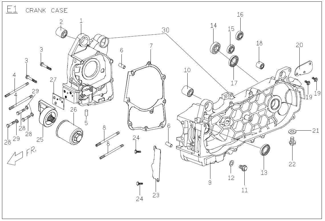
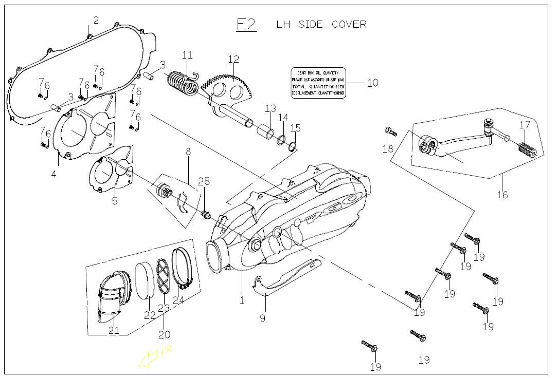
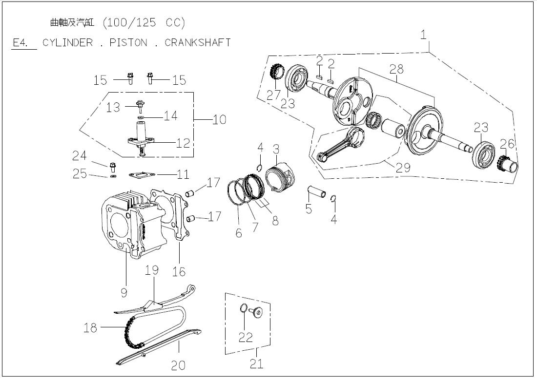
Official Factory Resource: Download the complete Genuine Buddy 50/125 Complete OEM Parts Manual (PDF) for official factory part numbers, exploded sub-assembly views, and fast-moving replacement references.