
1. The Mechanical Physics of Intake Flange Warping
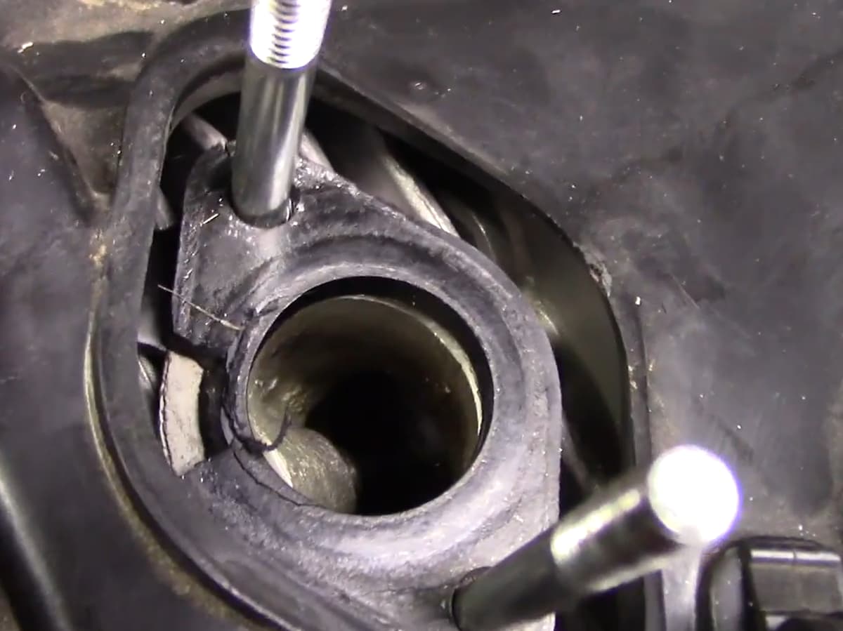
The intake tract of the Genuine Buddy 125 connects a Keihin CVK 24mm constant-velocity carburetor to the aluminum cylinder head intake port. Because small-engine vibrating masses create high cyclic fatigue loads, the OEM intake manifold utilizes a cast aluminum core encased in an NBR (Nitrile Butadiene Rubber) vulcanized boot. This composite structure is engineered to absorb engine vibration while maintaining an airtight seal at operating temperatures ranging from -10°C to 120°C.
When a technician tightens the two M6 intake manifold mounting nuts "by feel" using a standard 1/4-inch ratchet without a calibrated inch-pound or Newton-meter torque wrench, applied torque routinely exceeds 16 Nm to 22 Nm. This is more than double the OEM factory specification of 10 Nm (88.5 in-lbs).
2. Diagnostic Symptom Matrix & Lean Isolation Protocol
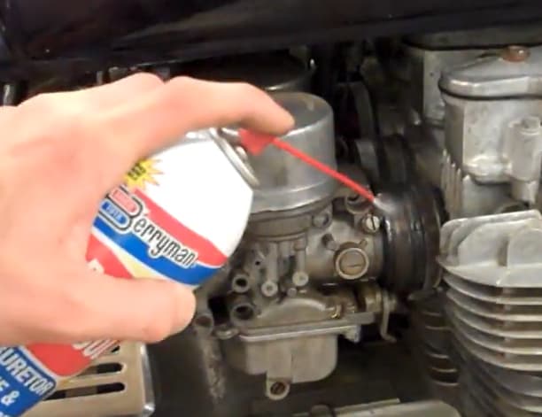
In accordance with Lean manufacturing root-cause analysis, technicians should systematically isolate vacuum leak symptoms before dismantling fuel delivery components. The table below correlates observed engine behaviors with intake tract physical integrity:
| Observed Symptom | Primary Root Cause | Secondary Effect | Verification Tool / Method |
|---|---|---|---|
| Hanging Idle / High Idle (2200+ RPM) | Unmetered air bypassing CVK butterfly valve | Extreme lean Air-Fuel Ratio (AFR > 16.5:1) | Unlit Propane Wand or Brake Cleaner Spray Test |
| Deceleration Popping in Exhaust | Post-carburetor vacuum leak on overrun | Unburnt oxygen igniting hot exhaust gases | Exhaust Gas Analyzer / AFR Wideband Sensor |
| Hesitation Upon Sudden Throttle Opening | Transient vacuum drop preventing slide lift | Vacuum diaphragm insufficient pressure differential | Dial Indicator on CVK Slide Lift / Smoke Generator |
| Hard Starting When Engine Is Hot | Thermal expansion enlarging flange gap | Vapor lock & ultra-lean cranking mixture | Infrared Pyrometer & Compression Tester |
To perform an authoritative smoke test without specialized shop equipment, pressurize the intake manifold to 3 PSI using a hand pump while feeding smoke into the vacuum port.
3. Factory Fastener Torque & Precision Installation Sequence
Eliminating repeat repair rework requires strict adherence to single-source-of-truth torque specifications. Never re-use an intake manifold base gasket once the joint has been unbolted. The metal core within composite gaskets crushes during initial torque application and cannot spring back to compensate for surface irregularities.
| Fastener Description | Thread Size | OEM Torque Spec (Nm) | OEM Torque Spec (lbf·ft) | Tightening Sequence / Pattern |
|---|---|---|---|---|
| Intake Manifold Flange Nuts | M6 x 1.0 | 10 Nm | 7.4 lbf·ft (88.5 in-lbs) | Alternating 5 Nm, then final 10 Nm pass |
| Carburetor Clamp Screw | M4 x 0.7 | 2.5 Nm | 1.8 lbf·ft (22 in-lbs) | Single pass; do not crush rubber boot |
| CVK Vacuum Nipple / Barb | M5 x 0.8 | 3.5 Nm | 2.6 lbf·ft (31 in-lbs) | Use medium-strength blue threadlocker |
| Airbox Duct Hose Clamp | M5 Screw | 2.0 Nm | 1.5 lbf·ft (18 in-lbs) | Hand tight with nut driver only |
Step-by-Step Precision Mounting Protocol:
- Surface Preparation: Clean the cylinder head intake mating surface using a precision ground stone or 600-grit sandpaper flat-blocked on a glass plate. Remove all residual gasket material until surface flatness tolerance measures within 0.03 mm.
- Gasket Inspection: Inspect the new OEM phenolic insulator spacer and green paper gasket. Ensure the vacuum impulse hole aligns perfectly with the cylinder head gallery.
- Thread Inspection: Chaser-clean the M6 cylinder head studs to remove corrosion. Apply one drop of light machine oil to stud threads to ensure accurate torque conversion without thread friction binding.
- Two-Stage Torquing: Install M6 flange nuts. Using a calibrated 1/4-inch drive beam or click-type torque wrench, torque both nuts to 5 Nm in an alternating left-right sequence. Proceed to the final pass of 10 Nm.
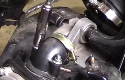
Figure 4: Torquing the intake manifold mounting nuts in an alternating sequence to the strict 10 Nm (88.5 in-lbs) OEM factory specification. Field Diagnostic Note: Compare these intake specifications with other popular urban platforms in our database, such as the Honda PCX 150 Master Guide or Honda Metropolitan CHF50 Guide. While Honda uses rigid aluminum manifold spigots with O-rings, the GY6 design depends entirely on the rubber boot integrity. Respecting the 10 Nm ceiling is the single most effective action a technician can take to guarantee 50,000 miles of leak-free operation.
4. Industrial Process Control & Preventative Maintenance
From an industrial maintenance standpoint, vacuum leak prevention is built into scheduled inspection intervals. Every 3,000 miles (5,000 km), technicians should inspect the rubber intake boot for surface checking (cracking caused by ambient ozone and ethanol fuel vapors). If surface cracks exceed 0.5 mm in depth when flexed by hand, replace the manifold assembly immediately before catastrophic lean detonation damages the piston crown.
By enforcing standardized torque values, eliminating non-approved chemical sealants, and utilizing precision measuring tools during every service intervention, mechanics can eliminate diagnostic guesswork and maintain factory-fresh throttle response on all GY6 and Genuine Buddy 125 scooters.

About the Author: Gregório
Industrial Administrator & Lean Manufacturing Consultant. Technology enthusiast passionate about bridging industrial process engineering with technical publishing. With a background in waste elimination, standardized specifications, and zero-rework quality control, Gregório curates the Motor Scooter Parts technical database to provide mechanics and DIY riders with field-tested OEM torque tolerances and precision diagnostic standards.